Stick Diagram Of Parity Generator Parity Checker Logic Circu
Parity mealy circuit Parity checker Figure 1 from 3-bit digital electro-optic odd parity generator based on
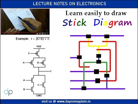
Tutorial on Stick Diagram to design CMOS VLSI Gates | Day On My Plate
Logic circuit truth table generator Stick diagram cmos vlsi gates Generator parity diagram even machine state conceptual
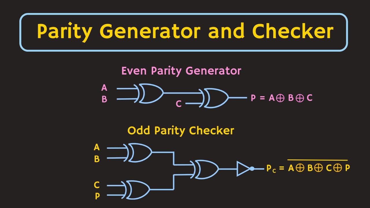
Parity generator and parity checker
Even and odd parity generators explained: working, truth table, circuitParity generator and parity checker : logic circuits and their types Parity generator diagram logic checker binary bit odd figure parallel tableParity nmos.
8 bit parity generator circuit diagramParity generator checker types logic even diagrams its Step by step method to design a combinational circuit – vlsifacts4-bit even parity generator.

Parity checker interpretation boolean algebra
[solved] derive the circuit for a 3 bit parity generator with inputs aParity generator and checker Circuit design of parity generator – vlsifactsParity bit even generator.
Parity generator circuit even diagram spread wordVhdl tutorial – 12: designing an 8-bit parity generator and checker Find the parity of a number using python3 bit parity generator.

Parity checker vhdl circuits
Assign the proper even parity bit for 1010Vhdl tutorial – 12: designing an 8-bit parity generator and checker Electrical – how to draw stick diagram of a function – valuable tech notesImplementing a binary parity generator and checker with greenpak.
How parity generators and checkers work: a complete guideParity checker odd logic Parity oddDiagram stick circuit problem shown schematic color give solved code question answer.

Odd parity checker
Solved: problem 6 the stick diagram of a circuit is shown....Parity circuit Truth table and interpretation of a 3-bit parity checkerParity generator and parity checker : logic circuits and their types.
Download nmos parity generator stick diagramCombinational parity [diagram] circuit diagram 3 bit parity generatorParity generator odd.
Tutorial on stick diagram to design cmos vlsi gates
Parity generator electrical4u systemsDigital circuit and k-map of a three-bit-odd-parity generator Parity generator and parity checkerWhat is a parity bit? how to design a parity bit checker and generator.
Orologio \ sveglia dcf77 rtc 6 digit 7 segmentiParity odd checker technobyte Parity generator and parity checker : logic circuits and their typesState machine diagram for parity generator – vlsifacts.

Parity vhdl checker
Parity checker generator binary logic odd input serial implementing figure articles dataParity generator and parity checker circuits Parity python checks codespeedy mathematicsParity checker logic circuit generator types odd diagrams its.
Parity generator and parity checkerState machine diagram for parity generator – vlsifacts .


